





Automation controller
Capture states and measurements and use them to trigger local actions. From a scheduled enable signal to temperature-dependent switching, develop the logic you need with Blockly or JavaScript.
The compact foundation for local automation.
IOZER basic connects inputs, outputs, sensors and interfaces—with local logic, an integrated web interface and no cloud dependency.
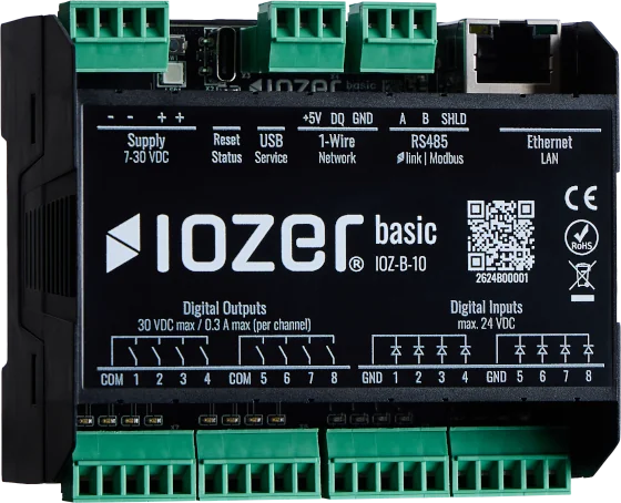
ONE DEVICE, MANY TASKS
IOZER basic combines digital inputs and outputs, 1-Wire sensors, Modbus and MQTT in a compact controller. A shared datapoint model connects the interfaces to your automation logic. Setup, programming and diagnostics take place directly in the local web interface.
Whether used as a standalone controller, a datapoint-based gateway or an addition to an existing installation: configure the functions your application needs. Automation runs on the device, without a mandatory cloud service or an additional feature licence.
Capture states and measurements and use them to trigger local actions. From a scheduled enable signal to temperature-dependent switching, develop the logic you need with Blockly or JavaScript.
Make values from connected devices available to other systems. For example, publish Modbus measurements via MQTT or map MQTT switching commands to a digital output. These mappings can also work without a custom logic program.
Read power measurements from a suitable Modbus meter and use them for your own threshold or enable functions. IOZER basic provides the interfaces and local programming environment; you create the energy management logic to suit your installation.
Integrate existing, electrically suitable push buttons, contacts and control inputs into new automation workflows. Add local logic and connectivity to higher-level systems to your existing equipment.
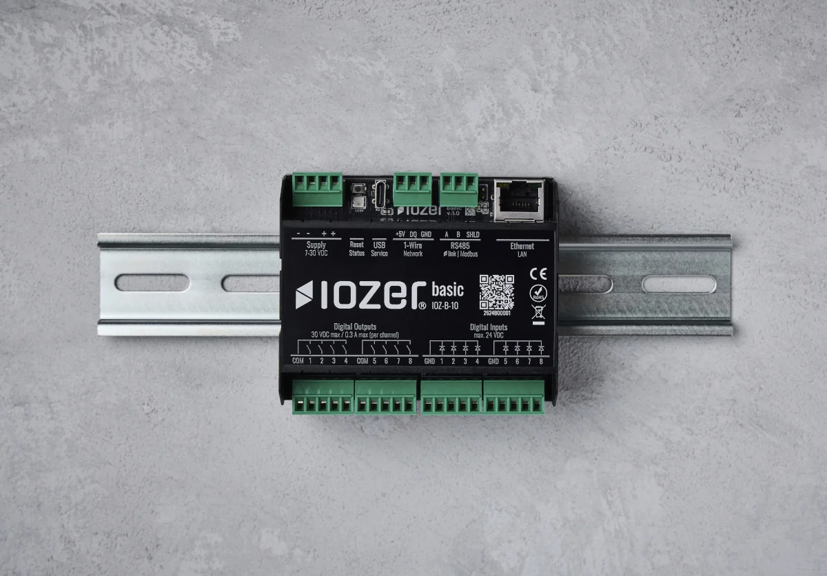
OPEN TO SENSORS AND SYSTEMS
Power supply, sensor bus, serial communication and network connection are located at the top of the device. Use the web interface to configure the interfaces you need and assign signals to your datapoints.
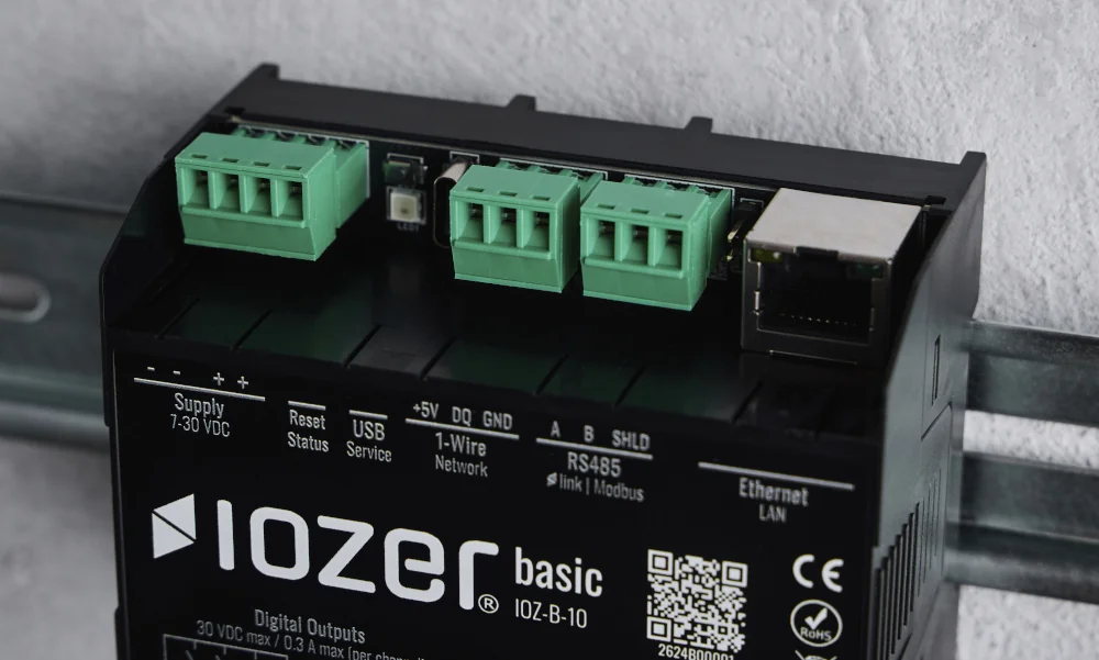
IOZER basic runs on an external 7–30 V DC power supply. A suitable 24 V DC power supply rated for at least 10 W is recommended. The supply terminals are duplicated to allow onward wiring.
The 5 V sensor connection provides a maximum of 500 mA. Sensors and other connected components must operate within their respective approved electrical limits.
Note: Use a suitable SELV/PELV power supply. Installation and electrical connection must be carried out by qualified personnel.
Connect supported 1-Wire sensors and start the sensor search in the web interface. IOZER basic detects the connected devices. Then select the measurements you need and create datapoints for them.
DS18B20 and DS2438 are supported. The DS2438 provides temperature, supply voltage VDD, input voltage VAD and voltage at the current-sense input VI. Additional quantities depend on the connected sensor module and the conversion required.
Factors and offsets allow you to adjust 1-Wire measurements. The software supports up to 32 configured devices. The practical bus installation depends on the sensors, power supply and wiring.
In master mode, IOZER basic polls configured Modbus devices. In slave mode, it provides mapped values to a higher-level master. The operating mode and serial communication parameters are configured in the web interface.
Datapoints connect registers to your application. This allows Modbus values to be used in local logic and made available for further integrations.
Outlook: IOZER link is planned as a future extension and is not yet part of the available functionality.
Connect IOZER basic to your network using either Ethernet or 2.4 GHz Wi-Fi. A Wi-Fi access point and the Ethernet interface are available for initial setup.
Normal operation uses one of the two network interfaces. Automatic switching between Ethernet and Wi-Fi is not provided.
MAKE DATA AVAILABLE TO OTHER SYSTEMS
Modbus RTU and Modbus TCP can be used in parallel. Modbus TCP client and server modes are alternatives and cannot be active simultaneously.
IOZER basic can operate as either a Modbus TCP client or server. Register addresses and datapoints are mapped in the web interface. Coils, discrete inputs, holding registers, input registers and various number formats are supported. Factors, offsets and byte or word order can be configured.
Exchange measurements, states and switching commands with an MQTT broker using freely defined topics. MQTT 3.1.1, QoS 0/1/2, retain and a configurable online/offline message with Last Will are available.
For protected connections, IOZER basic supports a username and password as well as TLS with an uploaded CA. An additional client certificate can optionally be used.
Datapoints process simple numbers, boolean values and text. Selecting individual fields from more complex JSON messages requires custom program logic.
CAPTURE AND SWITCH DIRECTLY
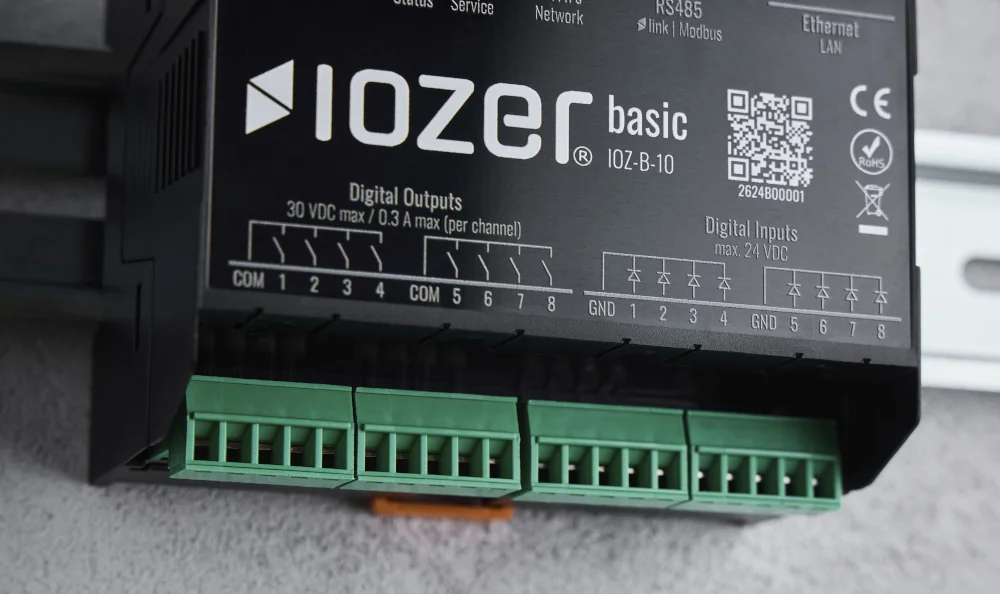
The eight relay outputs can switch suitable enable and control contacts. This is particularly useful for retrofits where existing devices are controlled through an external contact.
The outputs are arranged in two groups of four normally open contacts, each with a shared COM terminal. A maximum of 30 V DC and 300 mA is permitted per channel.
Larger loads can be controlled through suitable external relays or contactors. IOZER basic handles only the appropriate extra-low-voltage control circuit; switching voltage, current and load characteristics must match the permitted output ratings.
Important: Never connect mains voltage directly to the IOZER outputs. In particular, 230 V loads must not be switched directly through these contacts.
Switch an output off automatically after an adjustable time, for example for a time-limited enable signal. The switch-off time can be set from 0.1 seconds to 60 minutes. Optionally, another switch-on command restarts the timer.
This function is configured per channel and does not require a custom Blockly or JavaScript program.
For recurring switching pulses, on and off times can be set separately. Blinking starts when the configured output is switched on and ends when it is switched off, including by automatic switch-off.
Automatic switch-off and blinking are ordinary control functions, not safety-related shutdown functions.
The eight digital inputs capture suitable signals up to a maximum of 24 V DC. Signal interpretation can be inverted per input, and the debounce time can be set from 5 to 1,000 ms.
Button evaluation provides a click count. Single, double and multiple clicks can therefore trigger different actions. The detection pause is configurable.
An enabled counter datapoint counts rising, debounced edges. Counter values are stored in FRAM and restored after a restart. This allows pulses to be used in datapoints and automation workflows.
CONFIGURATION DIRECTLY IN THE BROWSER
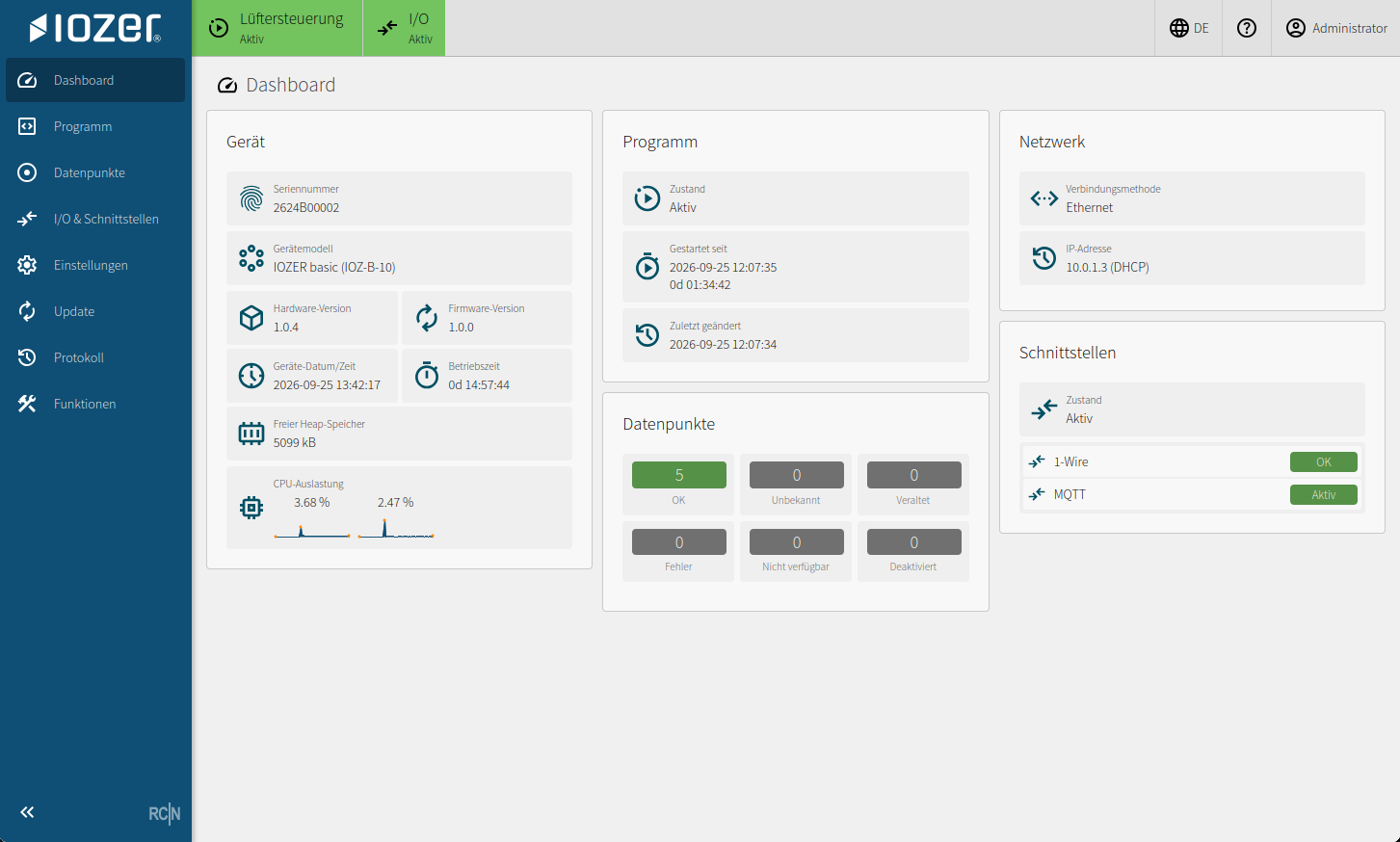
Configure interfaces, datapoints and automation logic in the local web interface. States, measurements and diagnostic information are available directly on the device.
Set up connections, check incoming values and observe the effect of your logic. Start and stop programs and test individual events. Logs and error details help with troubleshooting.
Firmware updates and configuration backups can also be performed through the web interface.
 Enlarge image
Configure interfaces, datapoints and logic.
Check states and measurements directly on the device.
Test events and use logs to investigate errors.
A SHARED LANGUAGE FOR YOUR SIGNALS
A temperature value remains a temperature value, whether it arrives via 1-Wire, Modbus or MQTT. IOZER basic brings these signals together in a shared datapoint model.
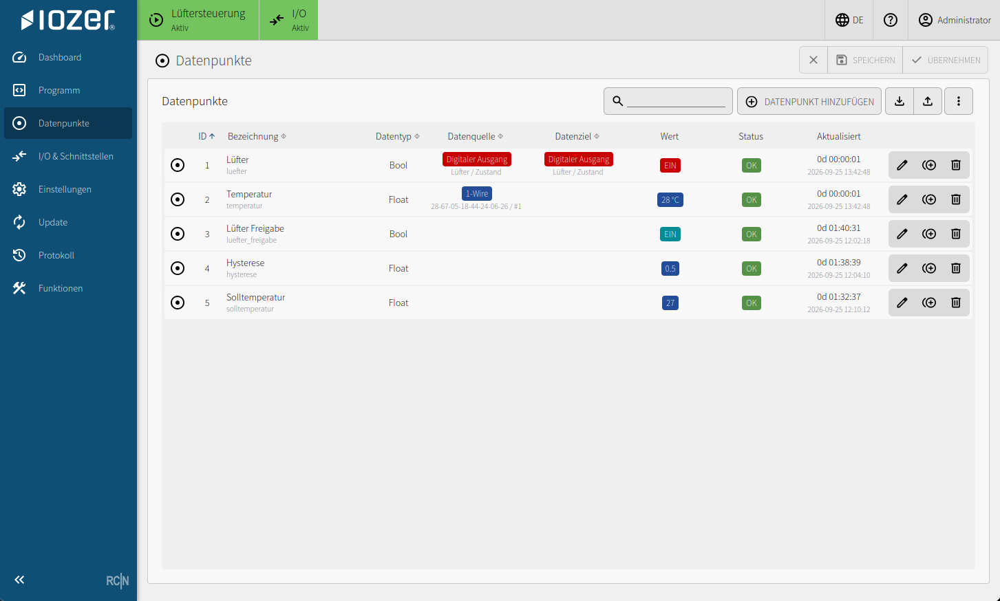
Up to 256 datapoints can represent local inputs and outputs, sensor values and communication data. Each value has a unique name and, where required, a description, unit, classification and suitable read or write mappings. Virtual datapoints without an external source are also possible.
In addition to the value itself, validity, quality status and the times of the last update and change are available. Your logic can therefore respond to status changes and errors as well as values.
Numeric and boolean values can be stored persistently. Excel import and export simplify the planning and editing of larger datapoint lists.
 Enlarge image
YOUR LOGIC. DIRECTLY ON THE DEVICE.
A datapoint change, an updated measurement, a schedule or a communication error: you define which events trigger your logic. The corresponding actions run locally on IOZER basic.
Program start and stop, as well as manually triggered events, can also be used. Buttons and counters are integrated through their datapoints.
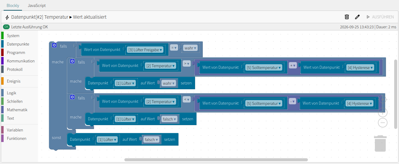
Connect datapoints, conditions and actions using graphical blocks. Create custom automation logic without having to write JavaScript.
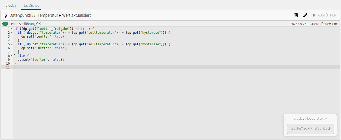
JavaScript is available directly in the browser for custom calculations and workflows. Here too, datapoints connect your logic to the attached interfaces.
Example
The temperatur datapoint supplies a reading from a 1-Wire sensor. The virtual solltemperatur and hysterese datapoints determine the switching thresholds; luefter_freigabe enables the control logic. The luefter datapoint is mapped to the digital output that switches a suitable low-voltage control input.
When enabled, the logic switches on above the setpoint plus hysteresis and off below the setpoint minus hysteresis. Between these thresholds, the previous switching state is retained. The demo project shown uses a setpoint of 27 °C and a hysteresis value of 0.5 °C.
 Enlarge image
 Enlarge image
The logic shown runs when the temperature datapoint is updated. Appropriate responses to invalid or faulty measurements must also be defined for the specific application. This example explains the logic and is not a protective function.
PROTECTION AT MULTIPLE LEVELS
IOZER basic combines local processing with protection for firmware, stored data and communication. Production devices ship with the production profile.
Secure Boot v2 and signed firmware verify the firmware at startup. Flash encryption in release mode and NVS encryption protect the corresponding storage areas.
User permissions and API tokens control local access. HTTPS with a dedicated certificate process is available for the web interface. TLS and an optional client certificate can be configured for MQTT.
IOZER basic has an individual device identity with a separate key and certificate process for manufacturer services. The device certificate is distinct from the certificate configuration for local HTTPS access and MQTT.
Security options are configured to suit the application. The availability of TLS or HTTPS does not mean that all interfaces automatically use encryption.
Safety and safe commissioningWORK LOCALLY. UPDATE FIRMWARE.
IOZER connect provides firmware updates and gives customers an overview of their devices. Configuration and automation logic remain local to IOZER basic.
Further IOZER connect services are not yet available. The local IOZER basic functions described here are included without an additional feature licence.
IOZER basic · IOZ-B-10
Specifications for firmware 1.0.0
These software limits describe configurable capacities. They do not replace verification of the actual bus installation, connected loads or timing requirements of an application.
Documentation and downloads
Electrical limits, connections, dimensions and technical specifications.
Open datasheetThe approved EU declaration of conformity for IOZER basic.
Open declaration of conformityInformation on connection, initial setup and safe operation.
Open quick start guideConfiguration, datapoints, interfaces and programming in detail.
Open documentationGood to know
Local configuration and automation logic do not require a mandatory cloud service. Locally connected sensors, inputs and outputs, and local network services can be used on site. Connections to external services need the respective network connection.
No. The local functions described are included with IOZER basic and do not require an additional feature licence. IOZER connect currently complements the device with firmware updates and a device overview.
No. Blockly lets you build workflows from graphical blocks. JavaScript is available as an alternative for writing your own logic.
No. The relay outputs are rated for a maximum of 30 V DC and 300 mA per channel. Suitable external relays or contactors are required for larger loads. IOZER basic switches a suitable extra-low-voltage control circuit, not mains voltage.
No. Integration uses configured datapoints and register mappings. Modbus RTU and Modbus TCP can run in parallel, but arbitrary telegrams are not forwarded transparently.
During normal operation, choose either Ethernet or Wi-Fi. Automatic switching after a connection failure is not provided. In setup mode, the Wi-Fi access point and Ethernet are available in parallel.
Counter values are stored in FRAM and restored after a restart. Numeric and boolean datapoints can also be stored persistently. Persistence is currently not available for text datapoints.
No. Program operation and input/output operation are separate. Stopping a program ends its logic but does not automatically disable the inputs and outputs. A desired shutdown response can be defined in the program stop event. The full startup, stop and timer behaviour described in the documentation must be taken into account.
IOZER basic provides interfaces and local programming for custom energy management tasks. A preconfigured energy management solution is not included. Thresholds, enable signals and other workflows are configured for the application.
No. IOZER link is planned as a future extension. The current RS485 functionality includes Modbus RTU.
IOZER basic
Connect sensors, existing devices and your own logic in a compact controller. With open interfaces, local processing and configuration directly in the browser.

ROCOON Automation GmbH uses essential cookies to operate this website securely. Google Analytics is loaded for audience measurement only with your voluntary consent.
You can change or withdraw your choice at any time through “Cookie settings” in the footer. Withdrawing consent has no disadvantages.

